
See stability
Loop gain and phase margin in power supplies and control loops ultimately reduce to a Bode plot.
MEASUREMENT INSTRUMENTS
RadiLab is developing the FRA-100, a frequency response and impedance analyzer for components, circuits, and systems. Two-channel stepped-sine sweeps, FPGA processing, and Ethernet SCPI make frequency-domain measurement more direct.

Form factor and UI are illustrative; final product subject to change.
WHY FREQUENCY RESPONSE
Frequency response describes gain and phase versus frequency; impedance reveals how components and networks behave across frequency. Putting both into one measurement workflow makes selection, debugging, and validation more efficient.
Loop gain and phase margin in power supplies and control loops ultimately reduce to a Bode plot.
The impedance of capacitors, inductors, resonators, and sensors changes with frequency, revealing ESR/ESL and resonance.
Magnitude, phase, and group delay of filters, amplifiers, and cables determine how a signal passes through the system.
CORE CAPABILITIES
FRA-100 starts with reliable two-channel measurement, then extends toward impedance, calibration, and VNA.
ADC1/ADC0 are sampled in sync. The ratio cancels common source and clock errors, keeping the result focused on the DUT.
Narrow-band detection at each point rejects out-of-band noise. Linear or logarithmic, start/stop or center/span, 201 points by default and up to 20,001.
Digital down-conversion and a single-bin DFT run inside the instrument; results return over 1 GbE.
TCP 5025 SCPI and a Windows host app; continuous sweeps, cursors, CSV/PNG export.
WORKFLOW
The current prototype covers connection, configuration, sweep, readout, and export. Calibration and fixture de-embedding are on the roadmap.
Connect over 1 GbE and set the instrument IP address.
Choose start/stop or center/span, linear or logarithmic spacing, point count, and receiver bandwidth.
Run a single or continuous sweep and watch magnitude and phase traces update.
Use the left and right cursors for frequency, magnitude, phase, and delta readouts.
Save CSV data or a PNG image for further analysis.
Calibration / normalization (in development): Open/Short/Load/Thru and fixture de-embedding will arrive with the impedance release.
APPLICATIONS
Each scenario is marked as available now or available with the impedance release, so you can judge fit for the current stage.
Measure input-to-output transfer, -3 dB bandwidth, resonance, and phase shift.
Measure node-to-node magnitude and phase with probes or injection.
Measure loop gain and phase margin to assess stability; an injection transformer is required.
Four-terminal impedance measurements reveal equivalent series parameters and self-resonance.
Impedance and resonance curves, Q factor, and resonant frequency.
Frequency-response labs, data export, and further analysis.
DEVELOPMENT ROADMAP
We first make gain and phase measurement reliable, then add impedance, calibration, and VNA. Every stage is validated on real hardware.
Stepped-sine source, two-channel ratio measurement, and the FPGA processing chain.
DoneTwo-channel gain/phase sweeps, 1 GbE SCPI, host software, and data export.
Current stageFour-terminal vector-cancellation balanced bridge (HC/HP/LC/LP), OSL/Thru, and fixture de-embedding.
In developmentFull two-port S-parameters, Smith/Nyquist, 1 Hz–120 MHz target.
PlannedABOUT RADILAB
Wuxi Ruilei Electronic Technology Co., Ltd. was founded in 2019 in Wuxi, Jiangsu. We work on electronics and RF technologies and now focus on measurement instruments.
FRA-100 is our first product. We started with frequency-response measurement and built a platform that combines the analog front end, FPGA signal processing, host software, and calibration methods.
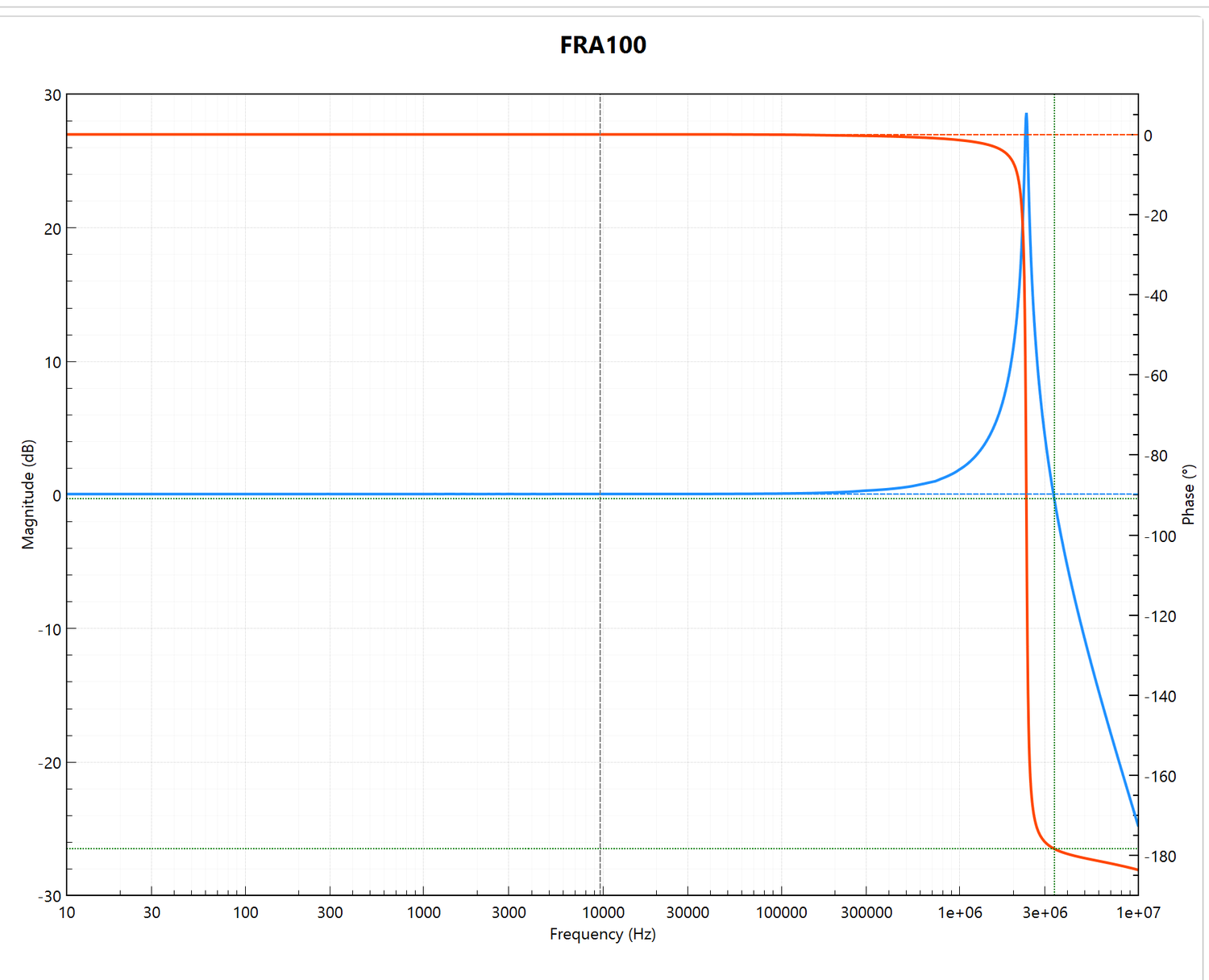
Measured: 10 Hz–10 MHz, 2,000 points, 100 Hz RBW, 50 Ω.
We are looking for early partners and test scenarios. Talk to us about prototype evaluation, joint testing, and distribution.